Let's Shape The Future Of Your Investments!
Natoque iaculis cursus augue urna commodo aptent morbi tortor porttitor quis ornare.
![Lithium-ion Battery Manufacturer | BAKTH Battery [Official]](https://bakth-battery.com/wp-content/uploads/2026/05/hideLogo.png)
![Lithium-ion Battery Manufacturer | BAKTH Battery [Official]](https://bakth-battery.com/wp-content/uploads/2026/05/logo.png)
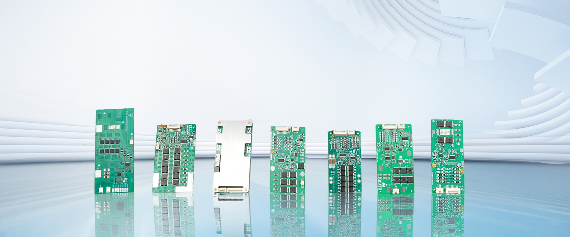
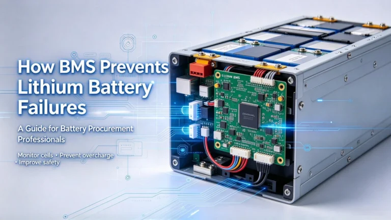
If you’ve ever wondered why smartphones, e-bikes, drones and portable power stations never instantly overheat or fail during charging or heavy use, the answer lies in their built-in battery protection board. This compact electronic circuit module serves as the safety brain for all lithium-ion and LiFePO4 battery packs.
Lithium cells deliver unmatched energy density but feature unstable chemical characteristics that make them vulnerable to damage under abnormal electrical or thermal stress. Without a protection board, even minor charging errors, short circuits or high-temperature operation can trigger swelling, permanent capacity loss or catastrophic thermal runaway.
The protection board runs continuous real-time monitoring of every critical battery parameter, automatically cutting power circuits the moment readings exceed safe operating limits. This round-the-clock oversight preserves battery performance, extends service life and eliminates life-threatening safety risks for residential, commercial and industrial battery applications.
Every standard protection board relies on four foundational electronic parts working in tandem:
| Component | Core Function |
|---|---|
| Protection IC Chip | The central processing brain; stores safety voltage/current/temperature thresholds and sends cutoff signals to MOSFETs |
| MOSFET Switches | Electronic power switches that instantly disconnect charge/discharge circuits during fault events |
| Capacitors | Stabilize circuit voltage and filter current fluctuations during high-load operation |
| Precision Resistors | Calibrate voltage sampling and balance micro current flow across the circuit |
Combined, these components deliver four layers of safety monitoring: overvoltage, undervoltage, overcurrent and short-circuit prevention, customized to match lithium cell chemical limits.
Temperature, voltage and current sensors are the critical data collection points on every protection board. They constantly feed real-time operational data to the main IC chip:
When any parameter crosses preset safe thresholds, the main IC immediately triggers the MOSFET switches to isolate the battery from chargers or external loads, stopping harmful chemical reactions before permanent damage occurs.
The protection board continuously tracks cell voltage while charging. For standard 3.7V lithium-ion cells, the safety cutoff sits at 4.4V maximum charging voltage. If voltage climbs above this limit, the MOSFET disconnects the charging input to block overcharge. Once cell voltage naturally falls back to a safe range, charging resumes automatically.
During device use, the board monitors minimum discharge voltage (typically 2.3V for lithium-ion). If load drain pulls voltage below this threshold, the discharge circuit cuts off to prevent irreversible anode lithium loss. The board also activates instant cutoff for sudden high-current surges caused by short circuits or overloaded equipment.
Overcharging is one of the top triggers for lithium battery swelling, electrolyte decomposition and thermal runaway. When cells absorb excess voltage beyond their rated maximum, lithium metal plates form on the anode, flammable gas accumulates inside the pouch/casing, and internal heat builds rapidly.
The protection IC enforces a hard upper voltage limit during charging. Once triggered, it blocks further power input until cell voltage drops back to normal. This simple safeguard drastically reduces long-term cell degradation and eliminates the risk of fire from sustained overcharging.
Deep discharge below the minimum safe voltage permanently ruins lithium cell structure. Draining cells to near-zero voltage strips usable lithium ions from the graphite anode, creating irreversible capacity loss that cannot be restored by recharging.
The protection board monitors voltage during every discharge cycle and disconnects the external load once the low-voltage threshold is hit. This feature is especially vital for seasonal gear like e-bikes and drones that may sit idle for months, as it prevents self-discharge from draining cells to dangerous levels.
Short circuits happen when positive and negative battery terminals make unintended contact, or internal cell damage creates conductive leakage paths. This generates extreme instantaneous current that spikes internal temperatures in seconds.
MOSFET switches on the protection board detect abnormal current surges within microseconds and fully break the circuit. This rapid response avoids melted wiring, cell rupture and flame propagation across multi-cell packs, a mandatory safety feature for high-discharge RC, drone and power tool batteries.
Lithium cells operate within a narrow safe temperature window; extreme heat or cold both accelerate chemical breakdown and safety hazards. Industry standard thermal limits for lithium-ion:
| Operating Condition | Safe Temperature Range | Risk of Exceeding Limits |
|---|---|---|
| Optimal Long-Term Performance | 15°C – 35°C (59°F – 95°F) | Balanced cycle life and consistent energy output |
| Max Safe Discharge Temperature | Below 45°C (113°F) | Above this threshold accelerates electrolyte breakdown and SEI layer overgrowth |
| Min Safe Discharge Temperature | Above 0°C (32°F) | Cold temperatures raise internal resistance and crack electrode materials |
| Critical Thermal Runaway Threshold | Above 90°C | High risk of separator melting and cascading cell failure |
Built-in thermistors feed real-time temperature data to the protection IC. If readings rise or fall outside approved ranges, the board cuts all power flow to cool the cell stack and prevent thermal runaway.
Many battery buyers and engineers confuse PCB, PCM and BMS terminology. The three systems serve distinct purposes, designed for single-cell consumer gear or large multi-series industrial battery packs.
A PCB is the bare physical substrate that holds electronic components and conductive copper traces. It acts as the physical foundation for all protection circuits.
A PCM is a complete low-cost single-cell protection board pre-assembled on a PCB substrate.
A BMS is an advanced, multi-functional intelligent management system built for multi-series lithium packs built for multi-series lithium packs (4S, 12S, 24S and higher).
| Module Type | Core Functionality | Unique Features | Target Battery Configuration |
|---|---|---|---|
| PCB | Circuit substrate & wiring carrier | Copper conductive traces, component mounting base | All battery protection hardware (base layer only) |
| PCM | Basic single-cell safety protection | Overcharge/over-discharge/short-circuit cutoff, low cost | Single 3.7V lithium-ion/LiFePO4 cell |
| BMS | Full lifecycle intelligent pack management | Cell balancing, SOC tracking, wireless communication, multi-point thermal control | Multi-series (4S+) lithium battery packs |
Cutting corners by skipping a matched protection board creates irreversible damage and major safety liabilities for all lithium battery systems.
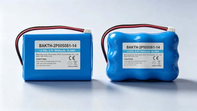
Unregulated overcharging causes continuous lithium plating on anodes, electrolyte decomposition and internal gas buildup that permanently swells pouch cells. Repeated deep discharge without low-voltage cutoff erodes the anode’s lithium intercalation capacity, leaving cells unable to hold full charge after just dozens of cycles. Without automatic circuit interlocks, there is no safety buffer to stop these damaging cycles.
Uncontrolled short circuits, fast overcharging and high-temperature discharge generate unregulated heat inside cells. With no thermal cutoff, temperatures can rapidly hit the separator melting point, triggering full thermal runaway. This leads to toxic gas venting, flame ejection and cascading pack-wide cell failure, creating fire risks for homes, warehouses and commercial vehicles.
After installing a new protection board, complete one full charge-discharge calibration cycle to confirm all voltage, current and thermal safety thresholds operate as designed.
Modern intelligent BMS platforms adopt modular, expandable designs compatible with small wearable single-cell packs all the way up to megawatt-scale energy storage systems. Key upgrades include dynamic fast-charging current matching, passive/active dual cell balancing and built-in heat dissipation linkage with pack cooling systems, improving overall energy utilization and multi-layer safety redundancy.
Advanced BMS hardware integrates embedded AI algorithms that analyze historical charge/discharge cycle data to predict cell aging speed and latent thermal faults weeks before visible failure occurs. Built-in IoT wireless modules enable real-time remote monitoring of voltage, temperature, cycle counts and SOC via mobile apps or cloud dashboards, widely deployed for shared mobility fleets, off-grid solar storage and industrial battery inventory management.
Global sustainability regulations are driving three major green innovations for protection boards:
Battery protection boards are non-negotiable safety hardware for every lithium-ion and LiFePO4 battery pack, delivering four core critical safeguards: overcharge, over-discharge, short-circuit and thermal protection. These circuit modules eliminate thermal runaway fire risks and extend battery cycle life by regulating all internal electrical and thermal activity.
To quickly differentiate the three mainstream battery circuit solutions:
The latest 2026 industry evolution centers on modular smart BMS, AI early fault prediction, IoT cloud remote monitoring and sustainable recyclable hardware materials. When sourcing lithium battery products for commercial or residential use, always verify the pack includes certified, matched PCM/BMS meeting UL, IEC and UN383 global battery safety standards.
If you need custom PCM and BMS solutions matched to your lithium pack voltage, current and application scenario, contact our engineering team for parameter matching, certification consultation and bulk quotation support.